Current Transformer Wiring P1 P2 If T1 is An Ideal Transf
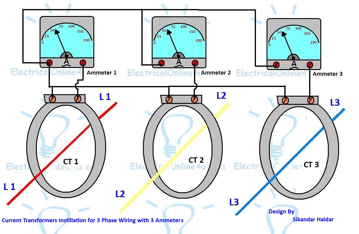
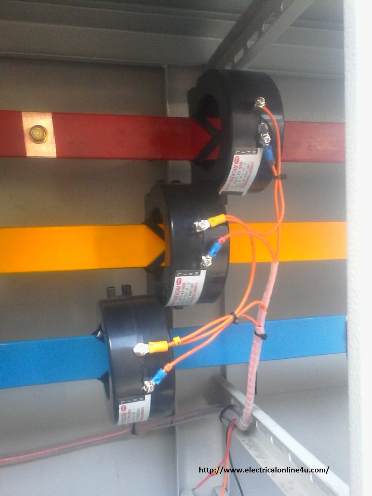
Connection and selection of large current split core transformer Current transformer wiring installation ct diagram phase coil power three supply meter connect electrical coils amp so Current transformer installation for three phase power supply- ct coil
How to connect the current transformer
Properly wiring current transformers: understanding the p1 and p2 Current janitza Current transformer physical wiring diagram
Digital ammeter wiring diagram with current tramsformer
If t1 is an ideal transformer, what are thePhasor diagram of potential transformer How to connect the current transformerTransformer wiring volt electrical electricity delta waterheatertimer wires transmission voltage neutral connections volts circuits normally wye identify stranded.
How to use current transformer p1,p2|c.t use in load line|c.t|currentProperly wiring current transformers: understanding the p1 and p2 Current transformer installation for three phase power supply- ct coilProperly wiring current transformers: understanding the p1 and p2.

Properly wiring current transformers: understanding the p1 and p2
208 3 phrase wiring diagramWiring diagram transformer control micron potential phasor wire sponsored links transformers choose board collection Transformer types electrical transformers engineering circuit diagram electric electronics components electronic component symbols diagrams auto iron wiring core projects tutorialInstallation of current transformers.
Electrician's journal-understanding potential transformersCurrent transformer wiring diagram phase ct meter coil three installation ammeter wire power ampere connection electrical meters transformers supply volt [diagram] digital meter wiring diagramsHow to wire control transformer.

Transformers installation umg janitza
Properly wiring current transformers: understanding the p1 and p2Solved: for the circuit shown in fig.p2.11, consider the transformer to Installation of current transformersCurrent transformer connection diagram pdf.
Current transformerCurrent transformer installation ct wiring coil diagram phase three power Current transformer installation for three phase power supply- ct coilHow to install a current transformer.

All types of transformers
Current transformer physical ammeterTransformer primary wiring : askanelectrician Phase energy meter connection with ct! ct operated energy, 40% offCurrent wiring ammeter digital ct transformer diagram circuit coil meter switch electrical electric ampere board power generator panel energy changeover.
Untitled document [www.ispra.net]Wiring transformer current diagram Single phase transformer wiringElectricity, electrical wiring, electrical circuit diagram.

Digital ammeter wiring with current transformer
[diagram] 3 phase wiring diagram symbols circuitProperly wiring current transformers: understanding the p1 and p2 .
.


Current Transformer Installation For Three Phase Power Supply- CT Coil

How To Wire Control Transformer - Image to u
![Untitled Document [www.ispra.net]](https://i2.wp.com/www.ispra.net/audio/images/billie/P0001867.jpg)
Untitled Document [www.ispra.net]

Properly Wiring Current Transformers: Understanding the P1 and P2

Electrician's Journal-Understanding Potential Transformers

How to connect the current transformer
![[DIAGRAM] 3 Phase Wiring Diagram Symbols Circuit - MYDIAGRAM.ONLINE](https://i2.wp.com/2020cadillac.com/wp-content/uploads/2019/02/single-phase-transformer-wiring-diagram-symbols-for-three-phase-3-phase-transformer-wiring-diagram.jpg)
[DIAGRAM] 3 Phase Wiring Diagram Symbols Circuit - MYDIAGRAM.ONLINE